

Flux-Cored Wire Manufacturing Machine
What This Machine Produces
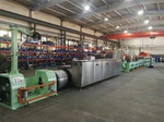
The production line is intended for manufacturing tubular flux-cored welding wires in which a metallic strip forms the outer sheath and a formulated flux or alloying core is enclosed inside the wire. Depending on the machine configuration and process specification, the line can be engineered for different flux-cored wire products, including gas-shielded and self-shielded types.


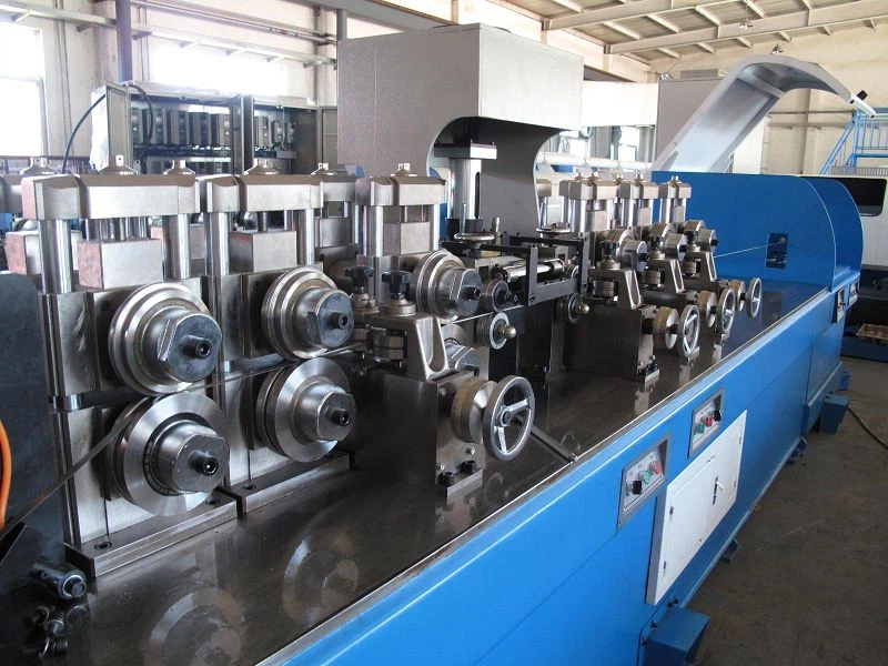
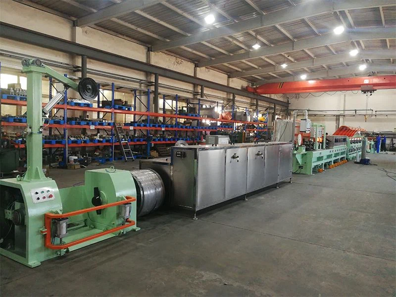
Flux-Cored Wire Production Process
A typical manufacturing route includes the following stages:
Metal Strip Pay-Off -> 2. Strip Straightening / Preparation -> 3. Strip Forming -> 4. Flux Feeding -> 5. Tubular Closing -> 6. Drawing / Sizing -> 7. Surface Treatment -> 8. Wire Take-Up -> 9. Spooling / Coiling -> 10. Inspection & Packing
Strip Preparation
The metallic strip is supplied continuously into the forming section. Strip width, thickness, surface condition and mechanical properties must be matched to the selected wire specification. Consistent strip feeding is important because variations at the input stage can affect tube forming and downstream dimensional control.
Tube Forming
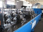
The strip is progressively formed into a tubular profile around the core material. The forming section must maintain stable geometry while the strip moves continuously through the production line. Forming stability becomes increasingly important when the line is operated at higher speeds or when smaller finished wire diameters are required.
Flux Filling
The formulated core material is continuously introduced into the formed strip. Flux filling is one of the critical process stages because the core content must remain within the specified production range. Feeding stability, material flow characteristics and filling control should therefore be evaluated together with the machine configuration.
Tube Closing
After the flux has been introduced, the metallic strip is closed around the core. The closing process must provide a consistent tubular structure suitable for subsequent drawing and sizing.
Drawing and Sizing
The filled tubular wire can pass through drawing or sizing stages to achieve the required finished diameter and surface condition. The number of drawing stages depends on the starting tube size, target wire diameter, material characteristics and required reduction.
Take-Up and Spooling
Finished wire is continuously collected by a take-up or winding system. Spooling requirements should be specified at the project stage because spool dimensions, winding pattern, package weight and final packaging format affect the take-up configuration.
Key Machine Configuration
A flux-cored wire production line should be configured around the product specification rather than selected only by nominal machine capacity.
|
Configuration Item |
Buyer Specification to Confirm |
|
Finished wire diameter |
Required diameter range |
|
Strip width |
Based on tube geometry and finished wire size |
|
Strip thickness |
Based on sheath construction |
|
Core material |
Flux / alloying formulation |
|
Filling ratio |
Required target and allowable variation |
|
Forming system |
Tube-forming configuration |
|
Closing system |
Required seam and tube geometry |
|
Drawing system |
Number of stages and reduction |
|
Line speed |
Required operating speed |
|
Production capacity |
Expected output by wire specification |
|
Take-up system |
Spool, coil or other package |
|
Control system |
PLC, HMI and process monitoring requirements |
|
Utilities |
Electrical power, compressed air, cooling and other services |
|
Layout |
Complete line footprint and equipment arrangement |

How to Select a Flux-Cored Wire Manufacturing Machine
Start with the Finished Wire
Do not select the machine from the advertised speed alone. First define finished wire diameter, wire classification, shielding method, core formulation, required filling ratio, spool or coil format, and target production.
Match the Strip to the Finished Wire
Its width, thickness, material, surface condition, and mechanical properties must be considered together with the forming process.
Evaluate Core Filling Control
For a flux-cored wire line, core filling is a process-control issue rather than simply a material-feeding function.
Compare Real Production Capacity
A machine's maximum mechanical speed does not automatically represent usable production output. Request capacity data based on a defined product specification.
Check Changeover Requirements
Evaluate which components require adjustment, which tooling must be changed, operator headcount, changeover duration, and control system storage settings.
Quality Control Points
Important inspection and verification points include:
Incoming Strip: Width, thickness, surface condition, material specification.
Core Material: Material formulation, particle condition, moisture condition where applicable, feeding characteristics.
During Production: Strip feeding, forming stability, core filling, tube closure, wire diameter, drawing condition, line speed, winding condition.
Finished Wire: Dimensional inspection, surface inspection, core filling verification, chemical composition, mechanical properties of deposited weld metal, welding usability tests, package and marking inspection.
FAQ